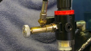
This is a solution to what is really a small problem on my compact airbrush compressor. I have made an isolation valve which will allow me to detach the airbrush easily for cleaning or replacement.
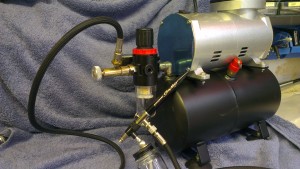
The compressor has an air pressure regulator fitted to the air receiver, but when the compressor is running and the air brush is connected, there is no way of swapping or cleaning the air brush without having to drain the receiver and then wait for it to re-charge up to pressure again.
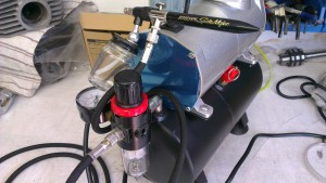
So to overcome what is a relatively minor problem, I needed some way of isolating the air briush from the receiver via some sort of isolating valve arrangement.
I did consider making a complete valve, but luckily, I found a small isolating valve from a test gas cylinder in one of my boxes of useful stuff! It has a flow meter and hose attached, which I don’t need, and is almost ideal for the job, but it will need a bit of tweaking to make it fit.
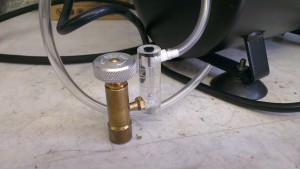
I had to take it apart and it is a lovely piece of machining, it is a needle valve (taper cone) and should allow plenty enough air flow for an airbrush.
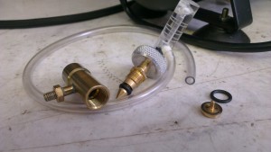
The bore will be enlarged, and a 1/8th” BSP threaded insert made of brass will be soldered into the body which will enable the valve to be screwed onto the pressure reducer outlet. There isn’t enough material to allow me to internally thread the body, it would be a bit too thin walled if threaded, and I wanted to keep threaded joints to a minimum because threads are a source of leaks. So I opted for an insert. The small diameter tee piece is a standard 5mm thread, the thread for the insert is 1/8″ BSP (a standard fitment thread).
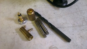
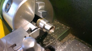
First operation is to bore out the main body for the insert.
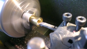
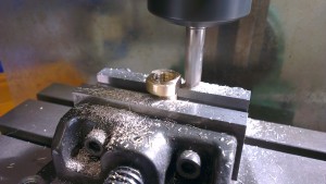
Machining the insert and threading 1/8″BSP
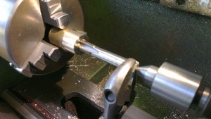
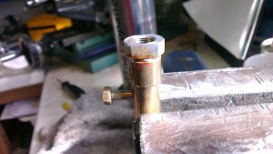
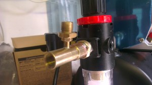
The valve is reassembled and connected to the pressure reducer. A leak test revealed some air escaping from the tee piece thread. I have now used a few drops of Loctite stud and bearing seal which has sealed it nice and air tight, but I may soft solder the fitting onto the tee piece in the future to reduce the number of threaded joints.
Now the valve is completed and assembled it works great, with plenty of air flow to the airbrush and no leaks. Now I can isolate the air supply, change airbrushes or hoses without the need to drain and refill the air receiver.
