Category Archives: Projects

Wheelchair cup holder

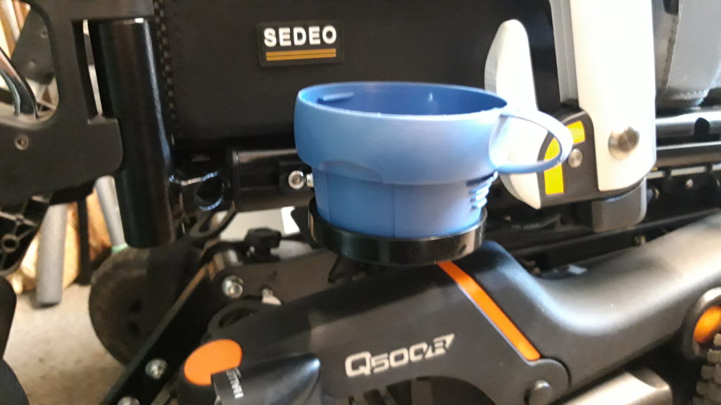
This cup holder has been specifically designed and made for an electric wheelchair user. I had already made a cup holder for an older wheelchair, but it would not fit the new wheelchair.
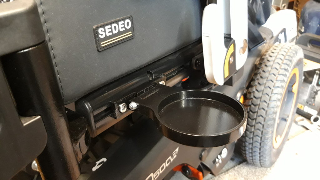
Using a mix of CNC and manual machines I started out with a piece of 12mm thick aluminium plate, then drew the basic cup holder shape In Vectric V Carve to produce the necessary toolpaths.

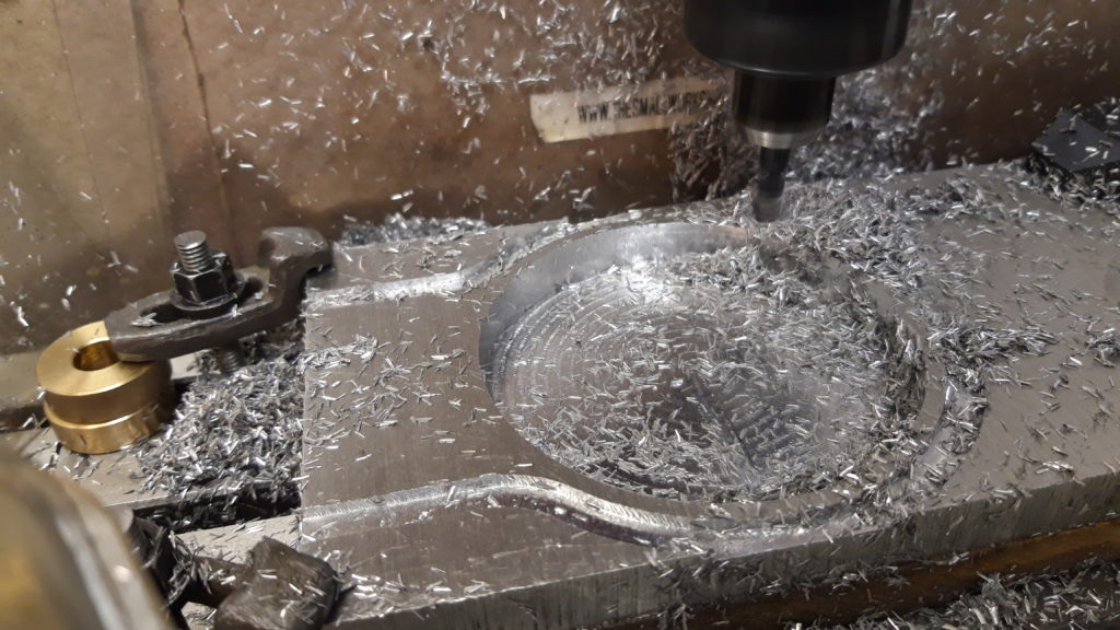
A 6mm end mill slowly cut out the 10mm deep pocket and the outer profile.
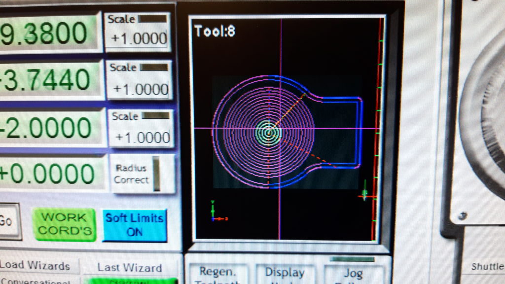
Vectric Vcarve is used to create the toolpaths
Pocket has been machined and now the outer profile is cut

With the main cup holder shape cut out, I took a piece of 18mm square aluminium and milled out the hinge bracket.
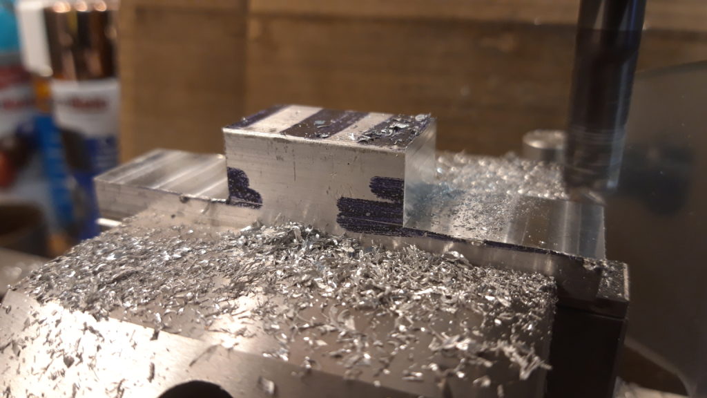
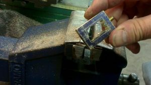
Hinge bracket

A slot was cut into the main cup holder shape to accept the hinge bracket, this needed some filing to make sure both parts could hinge properly.

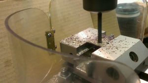
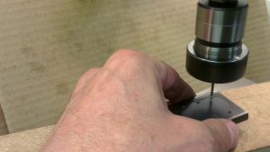
Then a 4mm diameter hole was drilled through both the cup holder and hinge.
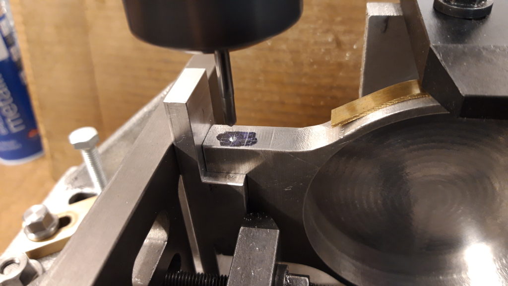
Drilling the hinge. With creative work holding!!!

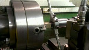
A special 4mm diameter hinge pin was made on the lathe, it has a small lozenge shaped head which will fit into a recess in the bracket, this acts as a anti turn device when the nut is tightened up.

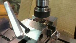
To make the cup holder stay in the upright position, I machined a slot in the hinge bracket to accept three small magnets which were glued into place. A smaller slot was milled into the cup holder to accept a small piece of mild steel bar, again glued into place. When filed down to a smooth surface the magnet and steel strip lined up perfectly to keep the cup holder upright when not in use.
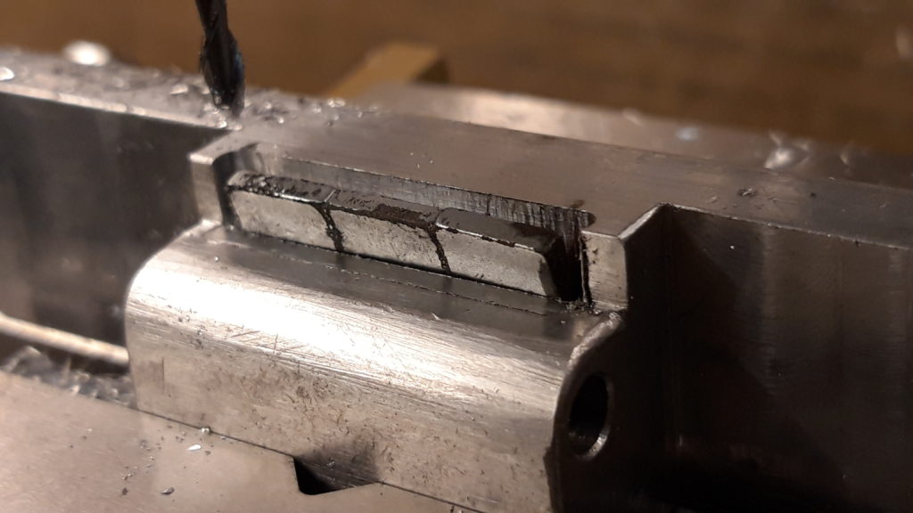
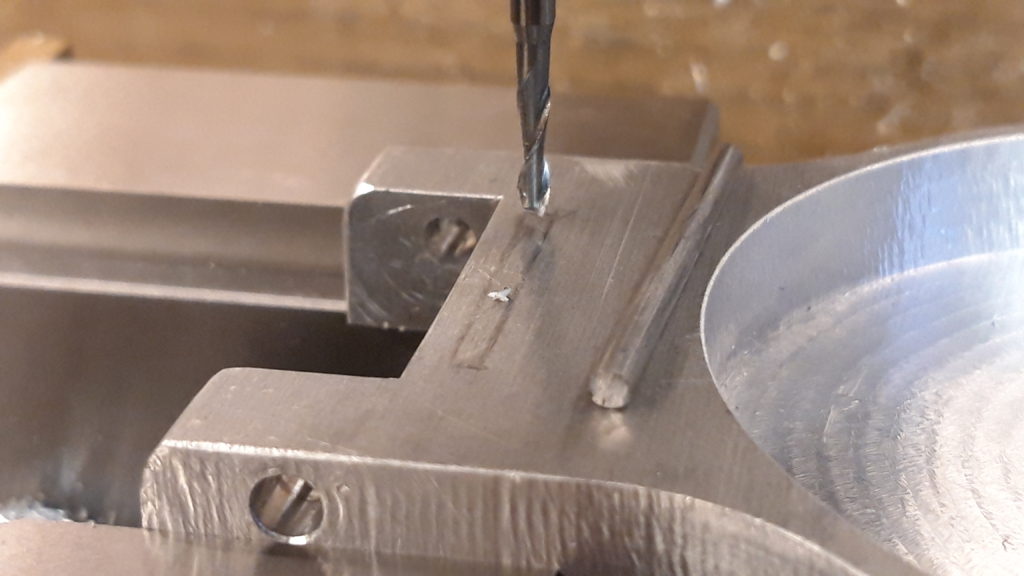
Three small magnets ready to be glued into the slot
Milling the slot for the steel bar

After few more test fits and filing sessions to get the fit right, making a keep plate for the two M6 cap head screws, and a final test assembly it was nearly time to paint it.
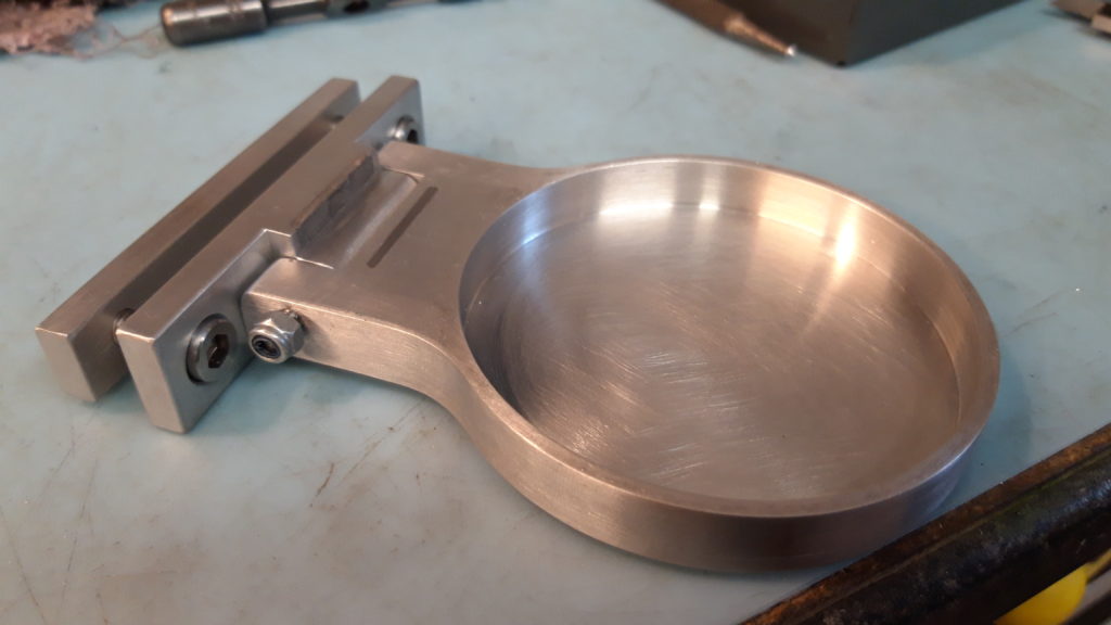
Final test assembly prior to painting

Painting was by using car spray paint and undercoat. The end result is petty good for me!

The keep plate slides into a ‘Tee’ slot on the wheelchair frame, and is held securely by the M6 screws. The magnets do a good job of holding it out of the way when not in use, but it is easy to drop the cup holder down to use it. And in a test the cup holder stays in the upright position even when going over bumpy ground.

Overall a very nice project which will definitely be used.
S&P part 3 ‘The Steam Chest’

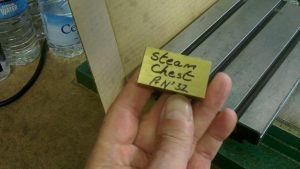
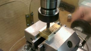
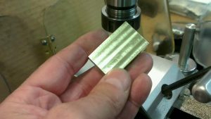
This is going to be the steam chest. It is made from a solid piece of brass flat bar. It is machined all over then marked out with the basic dimensions then machined to final size.

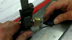
Using my homemade vertical height gauge the finish dimensions are marked out. A felt tip pen does a good job as marking out ink.

The four jaw chuck is used to align the offset screwed boss and 2mm Diameter hole. The boss is screwed 3/16″ x 40tpi for a steam fitting.

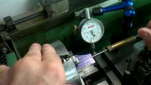
To align the centre of the offset hole I used a pointer mounted between the tail stock and centre pop. The square is used to align the faces of the brass block to the face of the chuck. Then final adjustment is made with the dial indicator.

The screwed boss is drilled and reamed 2mm diameter

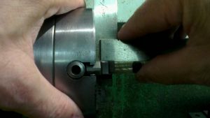
Screwing the 3/16″ x 40 thread with a die and holder supported by the tail stock to aid alignment.

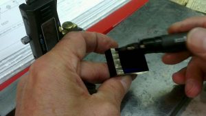
The centre oblong hole is drilled and sawed out to remove as much brass as possible, this makes the milling operation easier on the 6mm end mill. And it is quicker too!

The corners are sharpened up by using a 3mm end mill.

Two holes are drilled and tapped 2mm

And the bottom hole is drilled and tapped 3/16″ x 40 for a steam fitting.

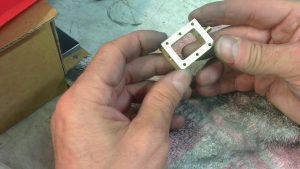
Six mounting holes are spot faced then drilled 2.2 clearance. The holes are located by using a small jig for accuracy. I will use this same jig on the steam chest cover and the piston housing.

After a final clean up with fine wet or dry, the steam chest is complete.

Tesla Valve

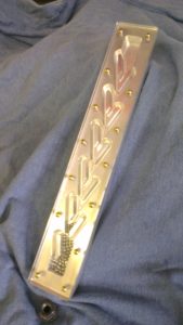
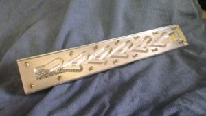
This is a reproduction of Nikola Tesla’s ‘Valvular Conduit’ more commonly known as the ‘Tesla Valve’.

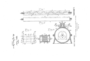
He patented this valve in 1920 but never actually made one! My reproduction has been copied from his original US patent. Some guesswork was needed as the patent drawings are not very sharp or crisp.

The buckets and diverter tabs are designed to offer resistance to liquid flow in one direction and preferential flow in the other, it works like a slightly leaking valve. It is often incorrectly referred to as a one way valve.

The ball bearings show how the tabs and buckets give resistance to the flow of liquid by getting trapped, resulting in a blockage in one direction. In the other direction the liquid flows very easily due to the angle of the diverter tabs giving a preferential flow.

Made of aluminium and perspex with brass screws and chromed ball bearings. Machined on the KX1 CNC mill.