Tag Archives: pitt

S&P part 3 ‘The Steam Chest’

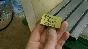
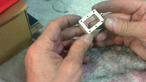
This is going to be the steam chest. It is made from a solid piece of brass flat bar. It is machined all over then marked out with the basic dimensions then machined to final size.

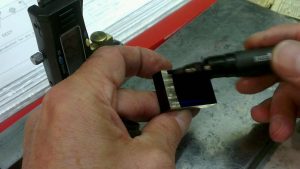
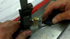
Using my homemade vertical height gauge the finish dimensions are marked out. A felt tip pen does a good job as marking out ink.

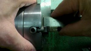
The four jaw chuck is used to align the offset screwed boss and 2mm Diameter hole. The boss is screwed 3/16″ x 40tpi for a steam fitting.

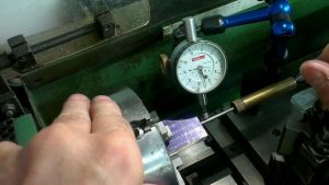
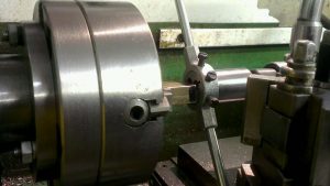
To align the centre of the offset hole I used a pointer mounted between the tail stock and centre pop. The square is used to align the faces of the brass block to the face of the chuck. Then final adjustment is made with the dial indicator.

The screwed boss is drilled and reamed 2mm diameter

Screwing the 3/16″ x 40 thread with a die and holder supported by the tail stock to aid alignment.

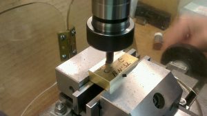
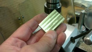
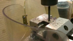
The centre oblong hole is drilled and sawed out to remove as much brass as possible, this makes the milling operation easier on the 6mm end mill. And it is quicker too!

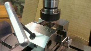
The corners are sharpened up by using a 3mm end mill.

Two holes are drilled and tapped 2mm

And the bottom hole is drilled and tapped 3/16″ x 40 for a steam fitting.

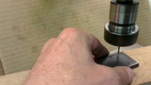
Six mounting holes are spot faced then drilled 2.2 clearance. The holes are located by using a small jig for accuracy. I will use this same jig on the steam chest cover and the piston housing.

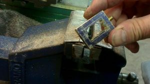
After a final clean up with fine wet or dry, the steam chest is complete.

Stothert & Pitt. About the engine

This model of the Stothert & Pitt Beam Engine is a 1/12th reproduction of the full size engine, which is still in existence, and preserved in Bath University.

Stothert & Pitt were manufacturers of steam engines in their Newark factory in Bath. This particular engine was exhibited in 1867 at the Paris International Exhibition.

The model is supplied as a kit of castings and blank bar stock. A comprehensive 99 sheets of drawings give the modeller the dimensions and assembly positions. Every part will require some sort of machining or finishing. The finished model will sit on a hard wood plinth, I will probably leave that until near the end of the project when I begin to assemble everything because one of the flywheel bearing blocks will be resting on the plinth.

The power will either come from steam, air or electric, I haven’t decided yet, although I would prefer steam, it would be more practical to use a battery and small electric motor via a pulley to achieve movement.

Painting will either be very impressive or a bit bland, I hope to achieve a good standard of paintwork using an airbrush or just by using a fine brush.

Keep watching I will be updating regularly.

Stothert & Pitt Part 1

I’ve actually started the Stothert & Pitt beam engine! I’ve had the kit for three years so it was about time I started it! There is post outlining a bit of information about the Stothert & Pitt company in the left margin.

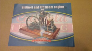
It should look something like this when completed:

IMAG0918

It’s a big project so expect a haphazard approach to uploading onto the small workshop site, because I’m not the most computer savvy bloke!

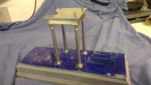
But anyway, here are a few photos of progress so far. The base has been marked out and drilled ready for threading. The tapered pillars complete with feet and brass finials are complete. Top plate is complete, and I’m part way through the cylinder bottom plate.

Progress so far: The base has been marked out and drilled ready to accept the cylinder, posts, bearings etc.

imag4393

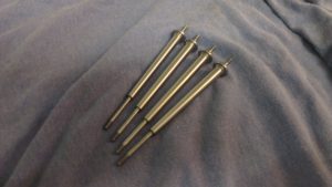
These are the four tapered beam support posts, they will have brass finials on top and a square base. They also need  1/16″ wide slot machined down their length to accept a decorative arches made of laser cut plate.

imag4395

They fit onto the base and support the top bearing block which will hold the beam and bearings in place.

imag4396

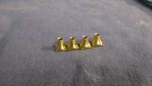
These are the four brass finials for the tops of the tapered  columns. These will also need a 1/16″ wide slot.

imag4399

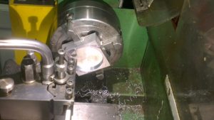
This is the cylinder base being machined on the Mini lathe. There is some more work to do to make it look more decorative.

Future posts will include photos and descriptions on machining the parts.