All posts by admin

Update and an Interesting job

Hi! Not posted for a while, over a year! Various things going on have got me out of the habit of posting stuff, but hopefully I will be posting regular again with a mix of CNC and manual machining.

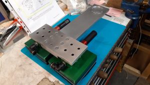
Here is a good example of the CNC/manual mix, this recent job is a ‘T’ shaped interface bracket for a robotic manipulator. Made of 12mm thick aluminium it needed drilling and countersinking. 6mm positioning dowels were used to give a rigid precise fixing. The circular recess is 2mm deep to enable the robot arm to locate securely, and is also dowelled and bolted into place. The two green/black foam pads are suction devices which will hold slabs of wood which will be positioned by the robot into two stages of machining.


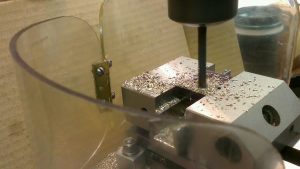
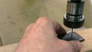
I used the KX1 to CNC mill the circular pocket and to spot drill the holes. Then I used the manual milling machine to drill and countersink the holes.  The 6mm dowel reamed holes were also done on the manual mill. After a quick file and polish with scotchbrite to give it a uniform finish everything fitted together great!

S&P part 3 ‘The Steam Chest’

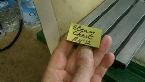
This is going to be the steam chest. It is made from a solid piece of brass flat bar. It is machined all over then marked out with the basic dimensions then machined to final size.

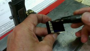
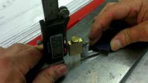
Using my homemade vertical height gauge the finish dimensions are marked out. A felt tip pen does a good job as marking out ink.

The four jaw chuck is used to align the offset screwed boss and 2mm Diameter hole. The boss is screwed 3/16″ x 40tpi for a steam fitting.

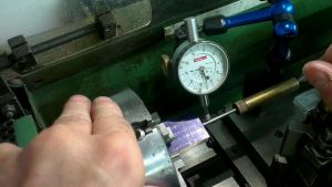
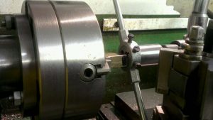
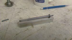
To align the centre of the offset hole I used a pointer mounted between the tail stock and centre pop. The square is used to align the faces of the brass block to the face of the chuck. Then final adjustment is made with the dial indicator.

The screwed boss is drilled and reamed 2mm diameter

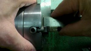
Screwing the 3/16″ x 40 thread with a die and holder supported by the tail stock to aid alignment.

The centre oblong hole is drilled and sawed out to remove as much brass as possible, this makes the milling operation easier on the 6mm end mill. And it is quicker too!

The corners are sharpened up by using a 3mm end mill.

Two holes are drilled and tapped 2mm

And the bottom hole is drilled and tapped 3/16″ x 40 for a steam fitting.

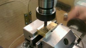
Six mounting holes are spot faced then drilled 2.2 clearance. The holes are located by using a small jig for accuracy. I will use this same jig on the steam chest cover and the piston housing.

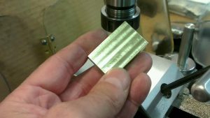
After a final clean up with fine wet or dry, the steam chest is complete.

CNC KX1 new spindle

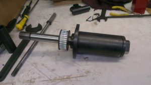
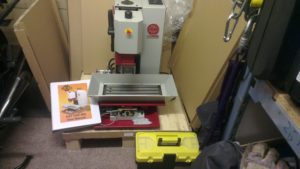
The all new spindle assembly has been fitted to the KX1 and is now spinning a lot sweeter and quieter. The run-out is negligible which is okay for a hobby machine tool.

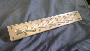
To test it out I have made the complicated ‘Tesla Valve’, which took about three and half hours to machine with a 3mm diameter end mill to machine the curves and tabs. CAD/CAM was done with Vectric Cut2D and Mach3 control.

See ‘Tesla Valve’ in the side menu

Tesla Valve

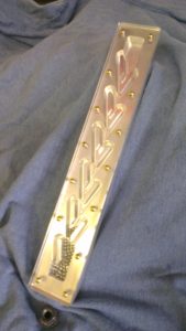
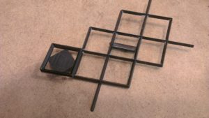
This is a reproduction of Nikola Tesla’s ‘Valvular Conduit’ more commonly known as the ‘Tesla Valve’.

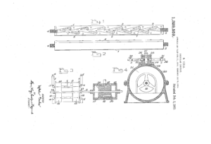
He patented this valve in 1920 but never actually made one! My reproduction has been copied from his original US patent. Some guesswork was needed as the patent drawings are not very sharp or crisp.

The buckets and diverter tabs are designed to offer resistance to liquid flow in one direction and preferential flow in the other, it works like a slightly leaking valve. It is often incorrectly referred to as a one way valve.

The ball bearings show how the tabs and buckets give resistance to the flow of liquid by getting trapped, resulting in a blockage in one direction. In the other direction the liquid flows very easily due to the angle of the diverter tabs giving a preferential flow.

Made of aluminium and perspex with brass screws and chromed ball bearings. Machined on the KX1 CNC mill.


CNC KX1 problems!

Jut to let you all know that I have had some issues with the KX1 CNC milling machine.

The spindle assembly had a run out of 0.002″ (two thousands of an inch) in the 2 morse taper bore, which doesn’t seem like much but when a drill or reamer is held in the spindle, the error is magnified. The result is unreliable dimensions and it is almost impossible to ‘tram’ or true up the Z axis. There should be zero runout.

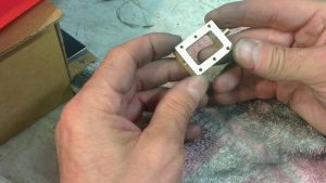
So for the past couple of months I have been in touch with Arc euro trade to come to a satisfactory conclusion.  One big problem was that the Arc Euro engineer who carried out repairs and diagnostics had been taken seriously ill, so they had nobody who they could call upon for an informed opinion.  So I dismantled the spindle assembly and sent it back to Arc for repair (see photo). It was sent back worse than it went!  So it went back again! I think the error is a combination of below standard bearings and the spindle housing machined out of true.
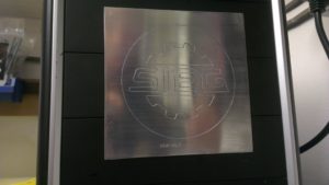
It is now 16 June 2017 and I am waiting on a brand new spindle assembly from Sieg in China. Hopefully this will solve the problem.

I hope to produce something soon!

Precision Tool vice

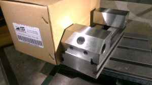
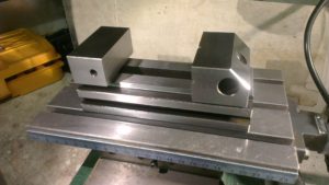
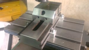
Here is a closer look at my new (ish!) 70mm Precision Tool Vice from Arc Euro Trade.

The 70mm wide jaws and compact size make it a perfect fit for the micro milling machine and the Sieg KX1.

The dimensions and squareness are absolutely spot on. The vice can also be used on end or on the side. When used on the side there is a very small clearance between the moving jaw and fixed jaw to allow the moving jaw to slide without rubbing on the bed.

Just one issue with it though! It’s too nice to use! I don’t want to scuff it up! ha ha!

Engraving bit holder

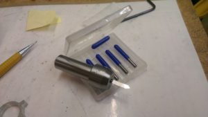
This is a small holder for 1/8th” diameter solid carbide engraving bits. Mainly to be used on the Sieg KX1 CNC, although it can be used on my Micro Mill.

Made out of 3/4″ diameter chrome moly bar it will fit into the ER25 collet chuck, held in by a 12mm collet.

The locating hole was made by using steadily larger drills as I haven’t got a 3mm diameter reamer, I used a 3mm drill. The surface finish was improved by using a small rolled up piece of emery cloth. The result is a smooth sliding fit with virtually no play at all.  Runout is about 3 tenths of a thou! pretty good I think.

A 3/16th” Whitworth grub screw is used to hold the bit firmly in place. A finishing touch was to stamp ‘1/8’ on the diameter.

I have a few engraving projects in the pipeline and will post them up here when I can.


S&P (Stothert & Pitt) Part 2 Slotting the columns

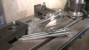
The tapered columns are slotted along their whole length to allow the laser cut side panels to slot inside them. So a fixture needed making.

The fixture is made from a block of aluminium

The taper needed supporting on some sort of fixture, so I made a simple holding clamp out of aluminium bar, and made three small clamps to hold the column firmly in place.

The completed fixture with the three clamps

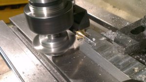
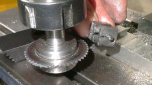
I used a slitting cutter 1/6th inch wide to cut the slots, this gave a nice fit for the 1.6mm wide plate after I polished both sides. Taking very small depth of cuts of about 10 thou, I cut down to full depth. The fixture worked very well on all four columns.

The four slotted columns

It seemed a shame that it wouldn’t be used again so I adapted it to hold the four brass finials and column bases which also needed a slot cutting into them.

I re-used the fixture to hold the brass finials because they needed slotting too
The mild steel column bases needed slotting too

Diamond shape Icing stamp

Something a little bit different. This is a cake icing decorating stamp, or more correctly it makes a diamond imprint into the icing to make a quilt type pattern.

A friend, who is a master cake maker, buys the propriety stamps which are flat, and made of a fragile plastic. They have a number of diamond shapes to enable a large area to be imprinted, but the problem is that the plastic breaks when imprinting a curved area. So I was asked to make one segment which would enable the imprint to be made with a lot more precision, and which could be built up as required.

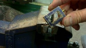
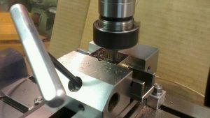
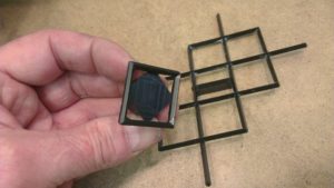
I made the stamp out of black Acetal which is food grade. It was a little trickier to make than I thought, because it is a diamond not a square, the sides are approximately 5 degrees off square. A 3mm end mill was used to rough out the middle and using the simple dividing head I angled the Acetal block to make the basic shape. I then used a small 90 degree chamferring cutter to make the sharp edges, and milled out the back face to make alignment easier. The chamferring cutter worked well on the outer edges, but left a radius on the inside edge which had to be cut out with a scalpel to give a sharp inner corner.

And just to prove it actually worked, the cake master made me a cake! It tasted as nice as it looks too!