All posts by admin

Milling vice clamps

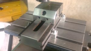
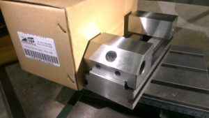
I have recently bought a precision tool makers milling vice. It is quite compact at 70mm jaw width but will do most of what I want to do on my machines.

imag4546

But I wanted to have dedicated table clamps for the new vice, and had to make some, four to be precise.

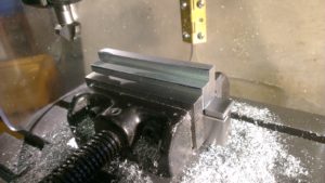
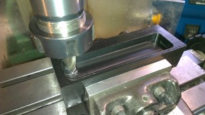
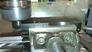
So starting out with a short piece of aluminium bar I milled a step into it, this is so the clamps will sit nicely on the table, the step is just proud enough to allow the clamping force to be exerted onto the vice and give a firm grip. In the photo a 45 degree chamfer is being machined along the long edges for a more pleasing look.

imag4549

The aluminium bar is cut into four pieces and milled on all sides to make all four pieces the same size.

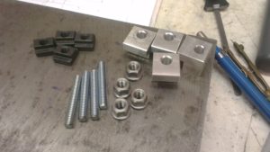
I am using 6mm hold down studs made from 6mm bolts. A clearance hole is drilled into each clamp.

I had four spare Tee nuts so I didn’t need to make those.

Now I need four 6mm washer faced nuts. These are made from a length of 1/2″ diameter free cutting mild steel.

imag4550

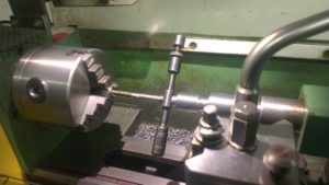
I machined them one at a time, transferring between the lathe and milling and back again, a bit tedious but it got the job done.

imag4551

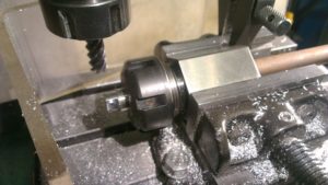
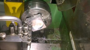
The hexagon flats were milled using the excellent ‘Stevensons collet block’ from Arc Euro Trade. All that is needed to make a hexagon is to grip the bar in the collet chuck and then mill a flat at the required depth and width, then undo the vice and rotate the collet block one flat and repeat until all six sides are completed. Then each nut was parted off in the lathe and chamfered.

imag4552

The clamps work well and although they are made from aluminium they should give long service in my small workshop, if they were subjected to any heavy work I would make them out of mild steel.

imag4553

Stothert & Pitt. About the engine

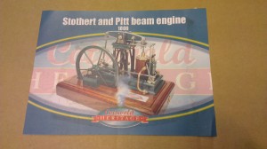
This model of the Stothert & Pitt Beam Engine is a 1/12th reproduction of the full size engine, which is still in existence, and preserved in Bath University.

Stothert & Pitt were manufacturers of steam engines in their Newark factory in Bath. This particular engine was exhibited in 1867 at the Paris International Exhibition.

The model is supplied as a kit of castings and blank bar stock. A comprehensive 99 sheets of drawings give the modeller the dimensions and assembly positions. Every part will require some sort of machining or finishing. The finished model will sit on a hard wood plinth, I will probably leave that until near the end of the project when I begin to assemble everything because one of the flywheel bearing blocks will be resting on the plinth.

The power will either come from steam, air or electric, I haven’t decided yet, although I would prefer steam, it would be more practical to use a battery and small electric motor via a pulley to achieve movement.

Painting will either be very impressive or a bit bland, I hope to achieve a good standard of paintwork using an airbrush or just by using a fine brush.

Keep watching I will be updating regularly.

Stothert & Pitt Part 1

I’ve actually started the Stothert & Pitt beam engine! I’ve had the kit for three years so it was about time I started it! There is post outlining a bit of information about the Stothert & Pitt company in the left margin.

It should look something like this when completed:

IMAG0918

It’s a big project so expect a haphazard approach to uploading onto the small workshop site, because I’m not the most computer savvy bloke!

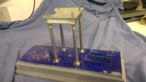
But anyway, here are a few photos of progress so far. The base has been marked out and drilled ready for threading. The tapered pillars complete with feet and brass finials are complete. Top plate is complete, and I’m part way through the cylinder bottom plate.

Progress so far: The base has been marked out and drilled ready to accept the cylinder, posts, bearings etc.

imag4393

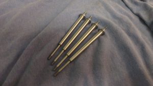
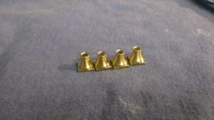
These are the four tapered beam support posts, they will have brass finials on top and a square base. They also need  1/16″ wide slot machined down their length to accept a decorative arches made of laser cut plate.

imag4395

They fit onto the base and support the top bearing block which will hold the beam and bearings in place.

imag4396

These are the four brass finials for the tops of the tapered  columns. These will also need a 1/16″ wide slot.

imag4399

This is the cylinder base being machined on the Mini lathe. There is some more work to do to make it look more decorative.

Future posts will include photos and descriptions on machining the parts.

Disabled camera adapter

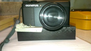
This is a bespoke adapter for a compact camera, which will allow a disabled photographer who has only the use of her left hand, to use her camera again.  I have also written it up as an article for issue 241 May 2016 Model Engineers Workshop.

http://www.model-engineer.co.uk/editorial/page.asp?p=250

Here’s a sequence of photos of the build:


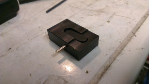
Roughing out the Acetal plastic cradle for the camera body
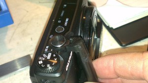
A relief radius needed cutting into the cradle to allow the rotating bezel to function
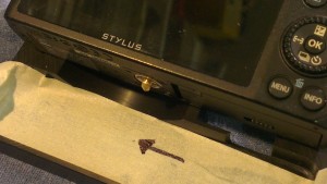
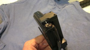
This shows the method used to locate the tripod securing screw location
This shows the method used to locate the tripod securing screw location. The base will be located through this screw hole (the thread is 1/4″ x 20)
The rotating left/right zoom control is on top of the camera, so I made a rough prototype fork to see if I could transfer the operation to a knurled wheel
This is a rocker which will operate the shutter button on top of the camera via a push rod and trigger
Top view showing position of zoom control fork and the aluminium push rod which will operate the shutter button via the rocker in the top plate
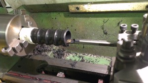
Boring out the handle to reduce weight. Finger grooves were machined using a 6mm radius cutter
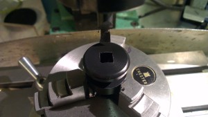
The zoom roting wheel needed a square hole cutting into it for positive location onto the zoom fork. Deep knurls were machined into the wheel
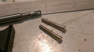
Two of the four 6BA cheese head screws which will hold it all together
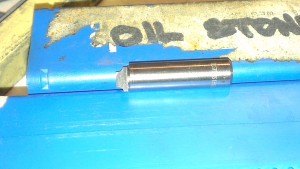
Homemade radius cutter to finish off the corners
Using the radius cutter on the base
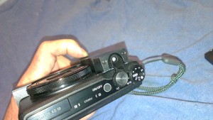
Assembled showing the added white reference line for the function dial
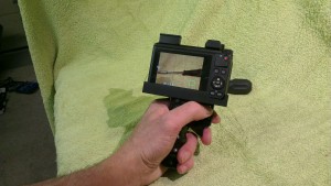
Assembled and held in the left hand as it will be used. This photo shows the location of the shutter trigger and the zoom wheel
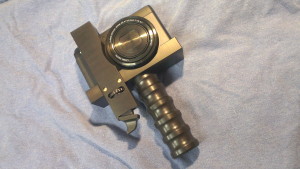
Completed assembly
Completed assembly