Category Archives: Uncategorized

Wheelchair cup holder

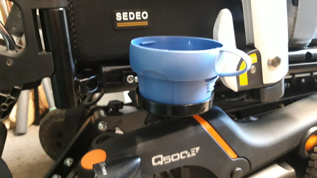
This cup holder has been specifically designed and made for an electric wheelchair user. I had already made a cup holder for an older wheelchair, but it would not fit the new wheelchair.
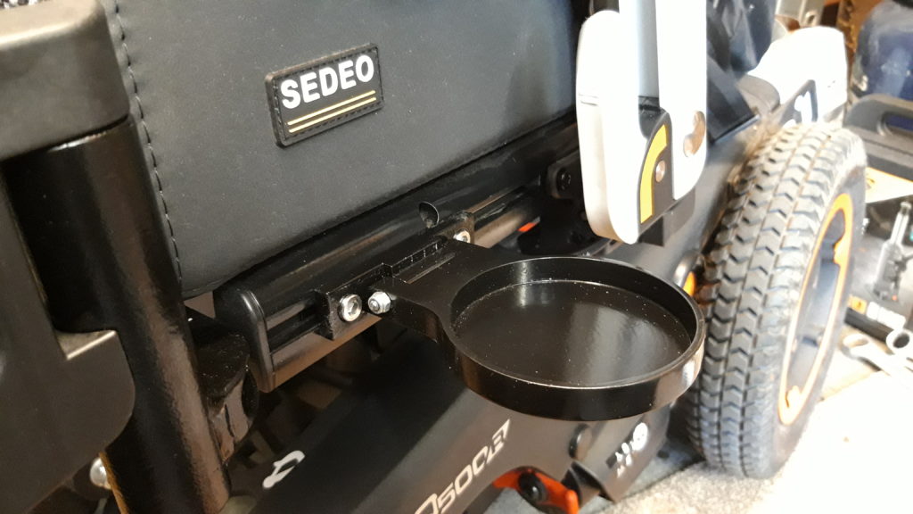
Using a mix of CNC and manual machines I started out with a piece of 12mm thick aluminium plate, then drew the basic cup holder shape In Vectric V Carve to produce the necessary toolpaths.

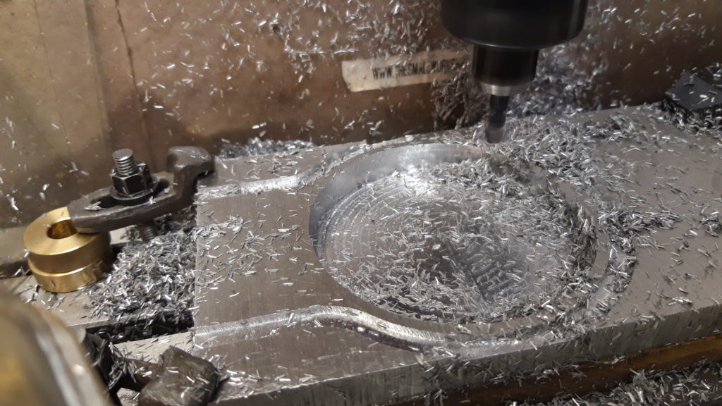
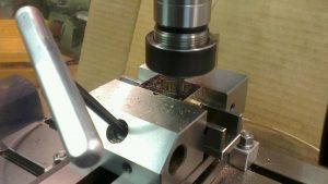
A 6mm end mill slowly cut out the 10mm deep pocket and the outer profile.
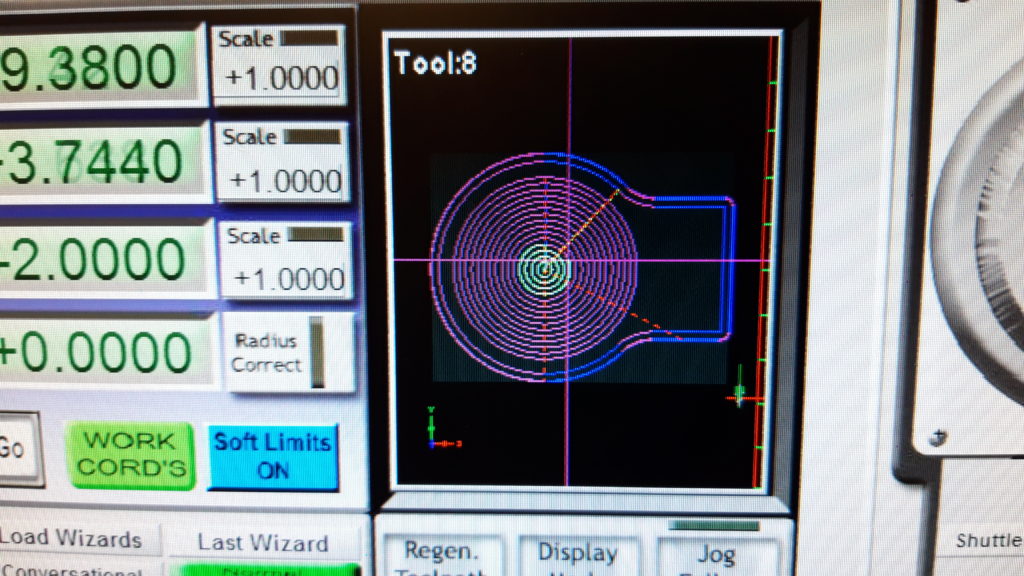
Vectric Vcarve is used to create the toolpaths
Pocket has been machined and now the outer profile is cut

With the main cup holder shape cut out, I took a piece of 18mm square aluminium and milled out the hinge bracket.
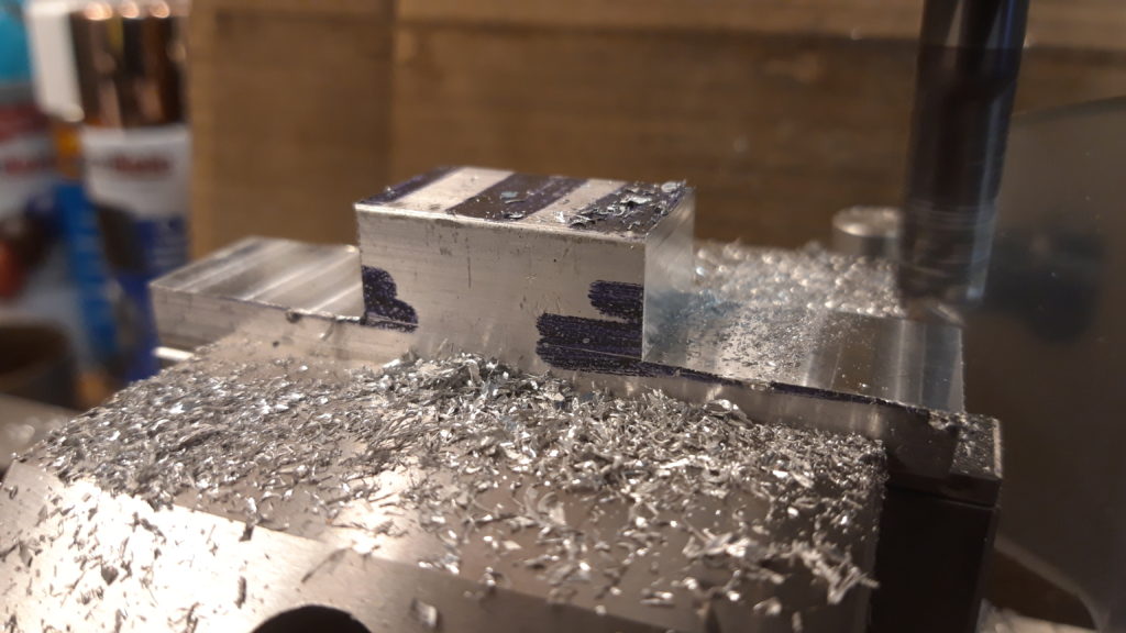
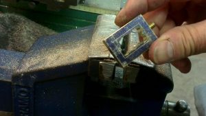
Hinge bracket

A slot was cut into the main cup holder shape to accept the hinge bracket, this needed some filing to make sure both parts could hinge properly.

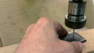
Then a 4mm diameter hole was drilled through both the cup holder and hinge.
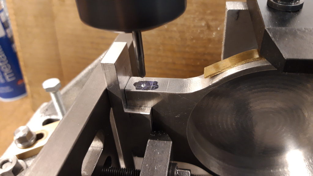
Drilling the hinge. With creative work holding!!!

A special 4mm diameter hinge pin was made on the lathe, it has a small lozenge shaped head which will fit into a recess in the bracket, this acts as a anti turn device when the nut is tightened up.

To make the cup holder stay in the upright position, I machined a slot in the hinge bracket to accept three small magnets which were glued into place. A smaller slot was milled into the cup holder to accept a small piece of mild steel bar, again glued into place. When filed down to a smooth surface the magnet and steel strip lined up perfectly to keep the cup holder upright when not in use.
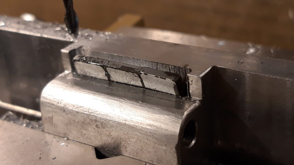
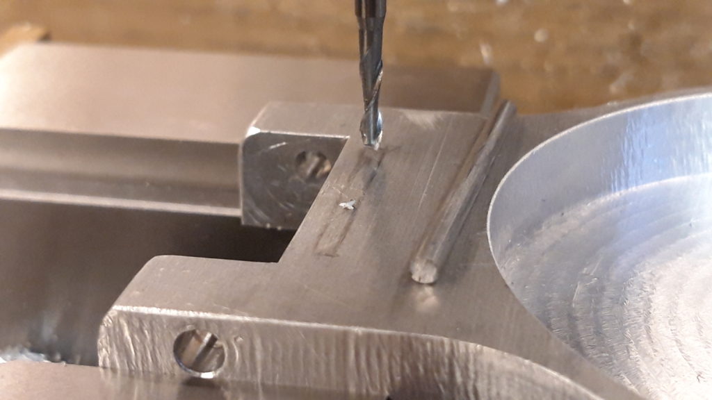
Three small magnets ready to be glued into the slot
Milling the slot for the steel bar

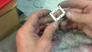
After few more test fits and filing sessions to get the fit right, making a keep plate for the two M6 cap head screws, and a final test assembly it was nearly time to paint it.
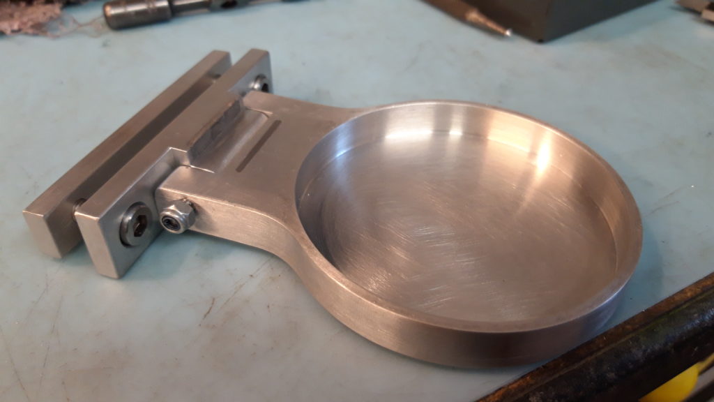
Final test assembly prior to painting

Painting was by using car spray paint and undercoat. The end result is petty good for me!

The keep plate slides into a ‘Tee’ slot on the wheelchair frame, and is held securely by the M6 screws. The magnets do a good job of holding it out of the way when not in use, but it is easy to drop the cup holder down to use it. And in a test the cup holder stays in the upright position even when going over bumpy ground.

Overall a very nice project which will definitely be used.
Impact driver bit

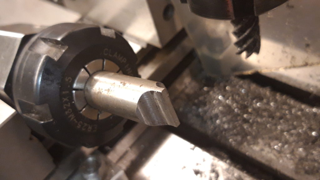
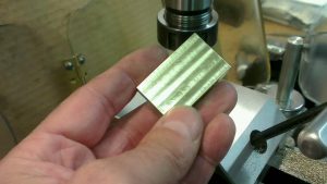
This is a little job making a impact driver bit out of 1/2″ diameter tool steel. I have a small selection of impact driver bits and needed a larger one with a flat blade. The flat is milled using a 10mm carbide end mill, taking equal amounts from both sides to produce a flat 0.065″ wide.

A hexagon is produced using the Stevenson’s collet block, which makes the process quick and easy. Then the bit is heat treated. Heating to a bright cherry red and quenched in water, making it glass hard. Then it is tempered to a light straw to somewhere around 50 rockwell C hardness. Chemically blackened using gun blue and the bit is finished. The photo below shows the largest bit in the bought impact driver kit on the left which is 10mm wide, compared to the new bit which is 12.7mm wide (1/2″)

Pokers!

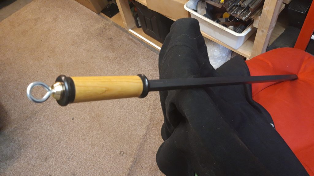
These are two pokers I have recently made for friends and family. Two slightly different styles, the long one has plastic ferrules with a 3/8″ square black mild steel poker and a bright plated hook. The other has brass ferrules with 10mm diameter bright mild steel poker and home made brass hook. Both have polished pine handles and are in regular use.

‘The Danny’

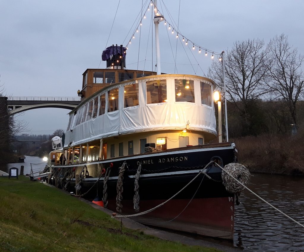
I have recently started volunteering on the steam boat ‘Daniel Adamson’ (The Danny). On the engineering team we are in the process of carrying out winter maintenance and inspections.

The Danny was built in 1903 at Cammell Lairds in Birkenhead UK. It is believed to be the oldest surviving Merseyside built steamship any where in the world.

The Danny is berthed in Cheshire at Sutton Weaver Swing Bridge, where winter repairs and inspections are being carried out.

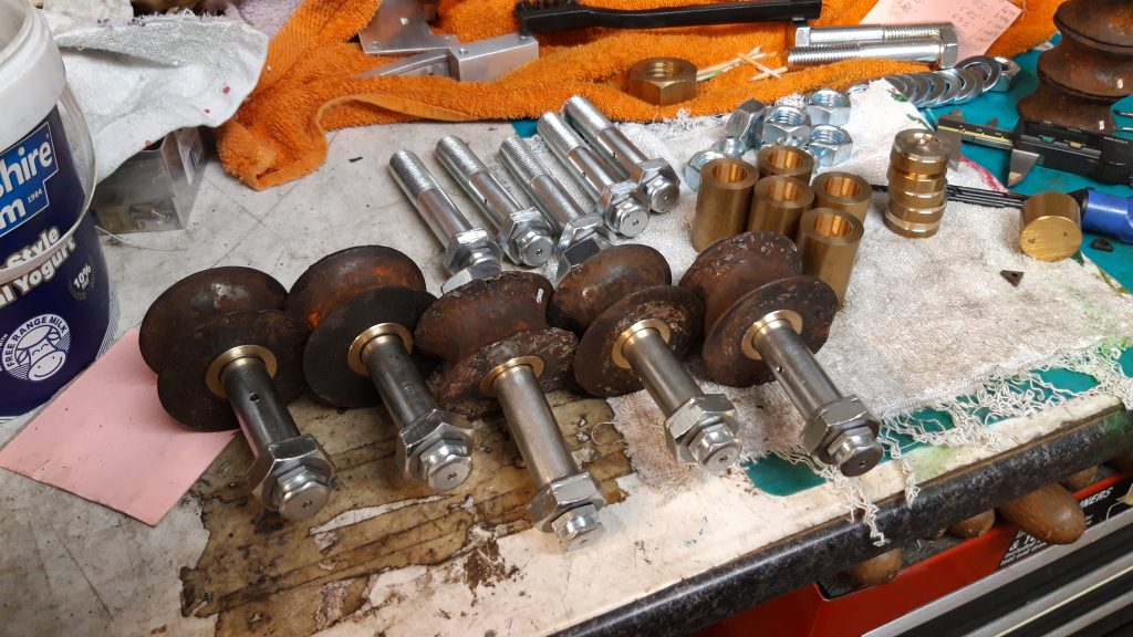
I have machined new brass bushes and adapted M16 bolts for grease nipples. These pieces will be re-fitted onto the steering gear guide rods which travel down each side of the boat to the rudder.

Other updates and photos to follow. For more information about the Danny click on the web link below.

https://www.thedanny.co.uk/

Tesla Valve

I have copied this page from the ‘CNC Milling’ category, mainly because I think Tesla invented such a clever device it deserves a page of its own. Have a look at the drop down menu ‘General Engineering’ (located above this page on the header)

RAF Roundel

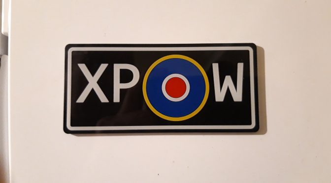
This is a fridge magnet or toolbox magnet depending where you want to stick it. The roundel is the design used by the RAF between 1942-47 used mainly on the fuselage, with different designs for the wings.

Made from reverse engraving plastic with the four colours painted on the back, it is a reproduction of the fuselage markings on RB396 Hawker Typhoon, the last surviving combat veteran of WWII.

A project to restore the plane to an airworthy state has begun, and it is expected to be airworthy in time for the 80th anniversary of the D Day landings. For further information have a look at www.hawkertyphoon.com.

Update and an Interesting job

Hi! Not posted for a while, over a year! Various things going on have got me out of the habit of posting stuff, but hopefully I will be posting regular again with a mix of CNC and manual machining.

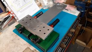
Here is a good example of the CNC/manual mix, this recent job is a ‘T’ shaped interface bracket for a robotic manipulator. Made of 12mm thick aluminium it needed drilling and countersinking. 6mm positioning dowels were used to give a rigid precise fixing. The circular recess is 2mm deep to enable the robot arm to locate securely, and is also dowelled and bolted into place. The two green/black foam pads are suction devices which will hold slabs of wood which will be positioned by the robot into two stages of machining.


I used the KX1 to CNC mill the circular pocket and to spot drill the holes. Then I used the manual milling machine to drill and countersink the holes.  The 6mm dowel reamed holes were also done on the manual mill. After a quick file and polish with scotchbrite to give it a uniform finish everything fitted together great!

S&P part 3 ‘The Steam Chest’

This is going to be the steam chest. It is made from a solid piece of brass flat bar. It is machined all over then marked out with the basic dimensions then machined to final size.

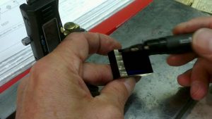
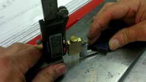
Using my homemade vertical height gauge the finish dimensions are marked out. A felt tip pen does a good job as marking out ink.

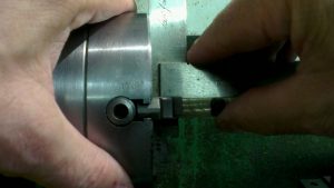
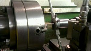
The four jaw chuck is used to align the offset screwed boss and 2mm Diameter hole. The boss is screwed 3/16″ x 40tpi for a steam fitting.

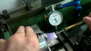
To align the centre of the offset hole I used a pointer mounted between the tail stock and centre pop. The square is used to align the faces of the brass block to the face of the chuck. Then final adjustment is made with the dial indicator.

The screwed boss is drilled and reamed 2mm diameter

Screwing the 3/16″ x 40 thread with a die and holder supported by the tail stock to aid alignment.

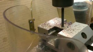
The centre oblong hole is drilled and sawed out to remove as much brass as possible, this makes the milling operation easier on the 6mm end mill. And it is quicker too!

The corners are sharpened up by using a 3mm end mill.

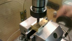
Two holes are drilled and tapped 2mm

And the bottom hole is drilled and tapped 3/16″ x 40 for a steam fitting.

Six mounting holes are spot faced then drilled 2.2 clearance. The holes are located by using a small jig for accuracy. I will use this same jig on the steam chest cover and the piston housing.

After a final clean up with fine wet or dry, the steam chest is complete.

CNC KX1 problems!

Jut to let you all know that I have had some issues with the KX1 CNC milling machine.

The spindle assembly had a run out of 0.002″ (two thousands of an inch) in the 2 morse taper bore, which doesn’t seem like much but when a drill or reamer is held in the spindle, the error is magnified. The result is unreliable dimensions and it is almost impossible to ‘tram’ or true up the Z axis. There should be zero runout.

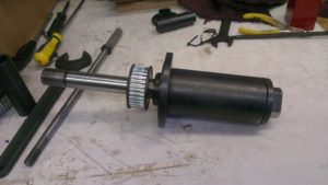
So for the past couple of months I have been in touch with Arc euro trade to come to a satisfactory conclusion.  One big problem was that the Arc Euro engineer who carried out repairs and diagnostics had been taken seriously ill, so they had nobody who they could call upon for an informed opinion.  So I dismantled the spindle assembly and sent it back to Arc for repair (see photo). It was sent back worse than it went!  So it went back again! I think the error is a combination of below standard bearings and the spindle housing machined out of true.

It is now 16 June 2017 and I am waiting on a brand new spindle assembly from Sieg in China. Hopefully this will solve the problem.

I hope to produce something soon!